Launch offer — valid today only

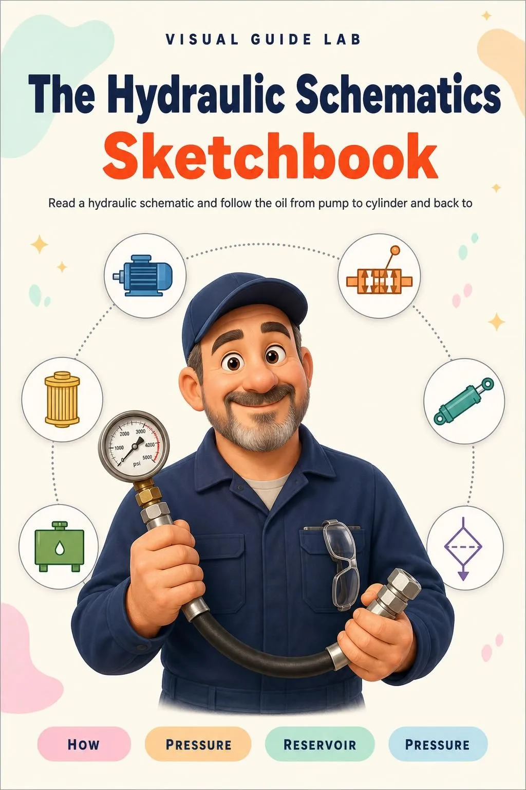
The Easiest Way to Read a Hydraulic Schematic With Every Circuit Drawn Step by Step!

Cylinder drifting down, slow loader, hot oil, noisy pump: the manual explains it in paragraphs. Here every topic fits on one page, drawn, with the oil traced from pump to cylinder and back to tank, from the first symbol to troubleshooting. 66 illustrated pages.

SHOW ME THE DRAWN PAGES

🔒 Secure checkout · PDF by email · 30-day guarantee

One topic per pageOne topic per page, every circuit traced in the same 5 steps
66 illustrated pages11 parts, from reading symbols to pneumatics
Up-to-date sourcesUS Army FM 5-499, US Navy NAVEDTRA 12964 and OSHA 29 CFR 1910.147

This Is What the Pages You Will Study Look Like

One topic per page, the drawing that shows you how it works and the boxes with what you need to know:

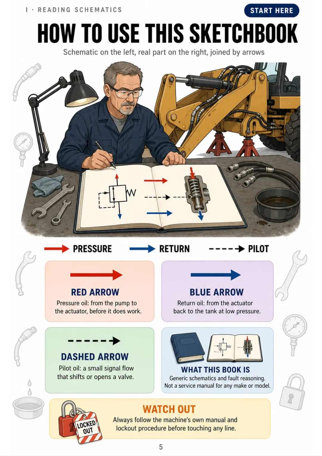
Red for pressure, blue for return, dashed for pilot: the same color code on every page.
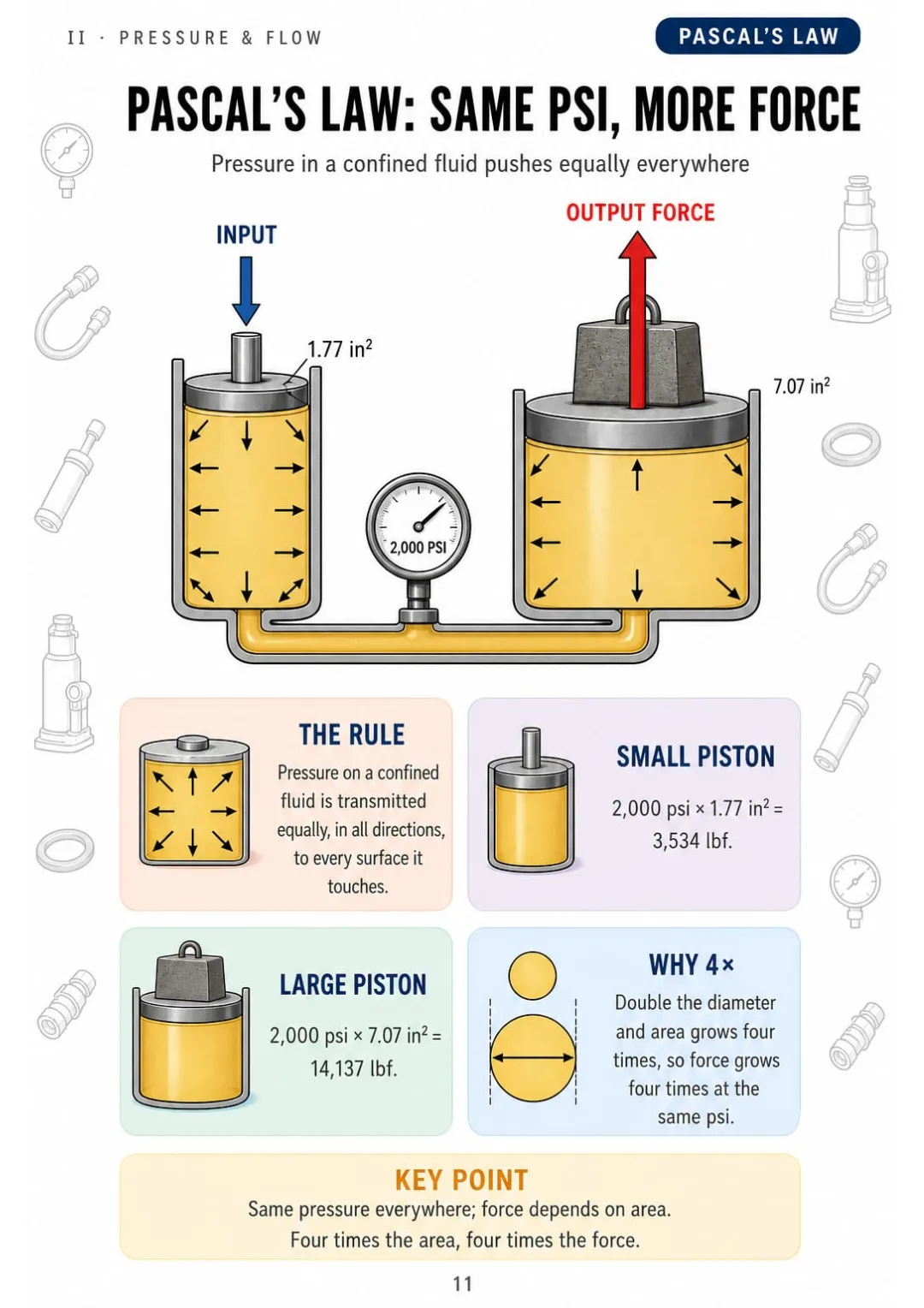
2,000 psi on 1.77 in² = 3,534 lbf; on 7.07 in² = 14,137 lbf.
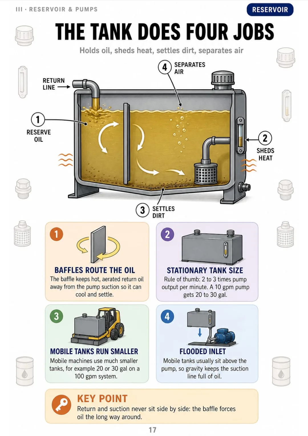
Stationary tank rule of thumb: 2 to 3 times pump gpm, with a baffle between return and suction.
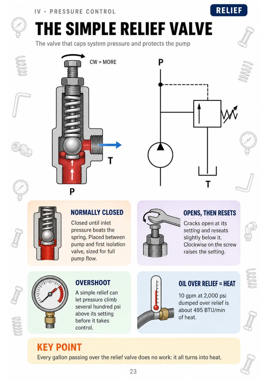
Normally closed, clockwise raises the setting, and 10 gpm at 2,000 psi makes about 495 BTU/min
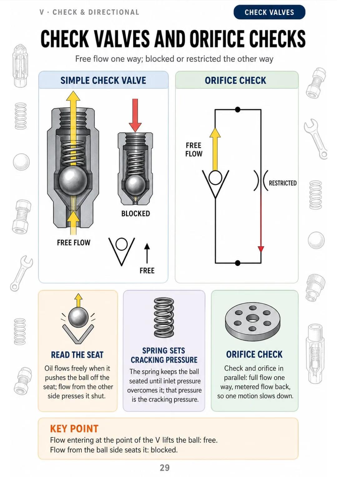
Check valve vs orifice check: free flow one way, blocked or metered back
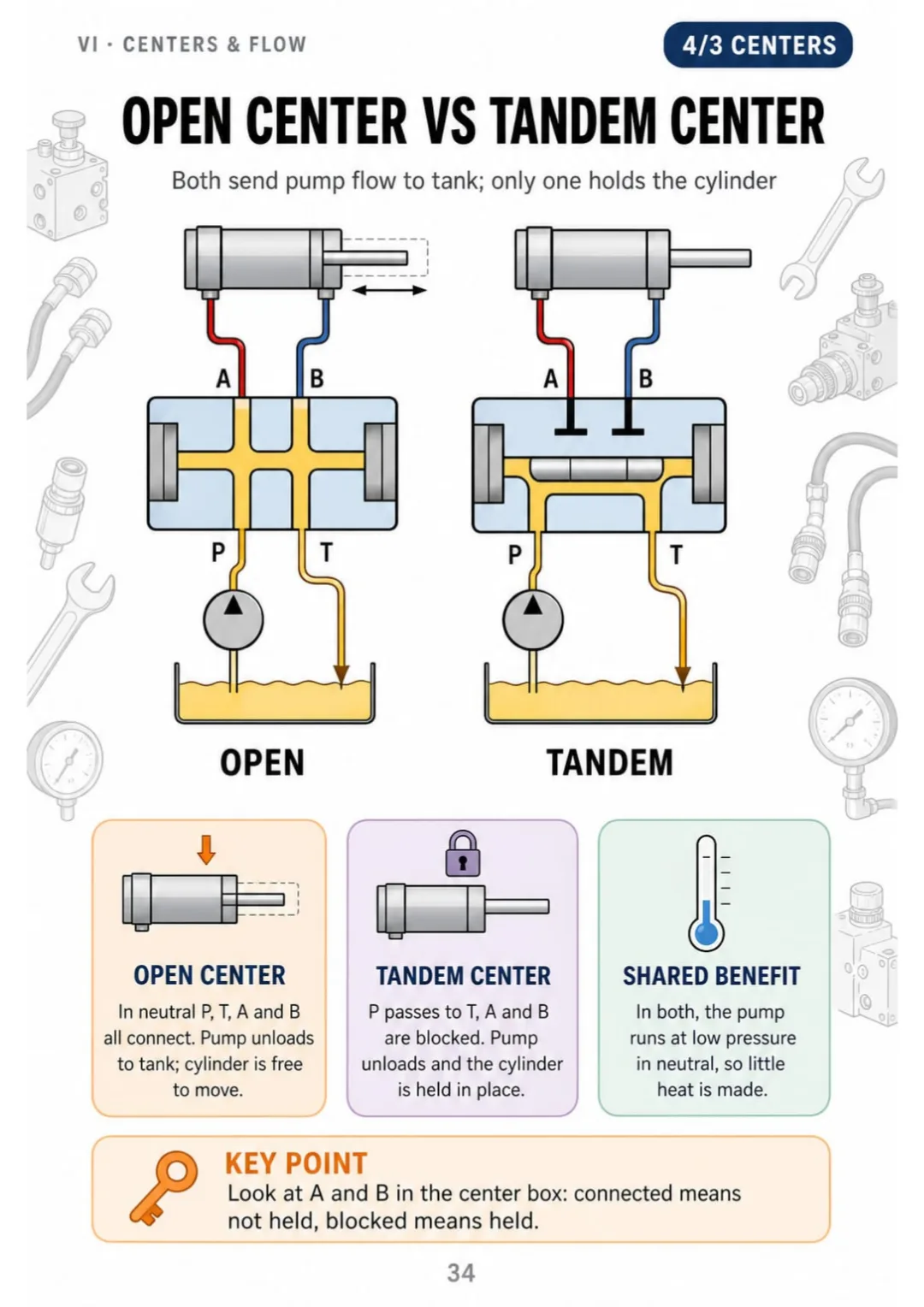
Open vs tandem center: same pump unloading, different cylinder holding
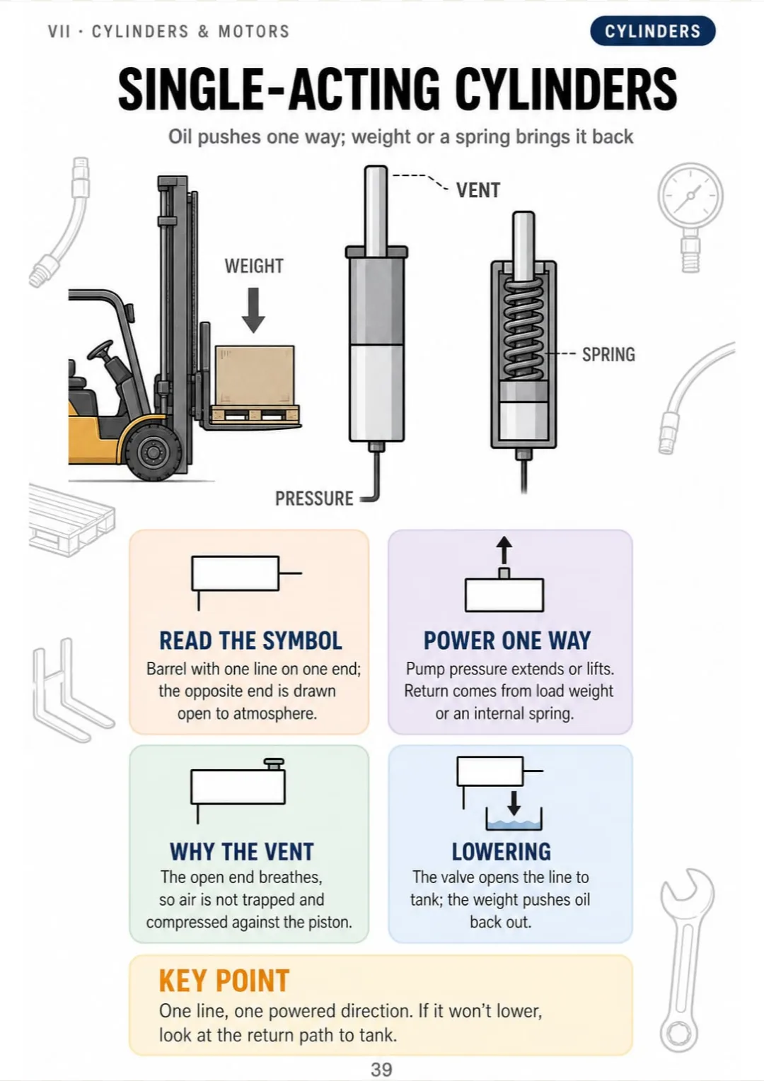
Single-acting cylinder: one working line, vented end, weight or spring return
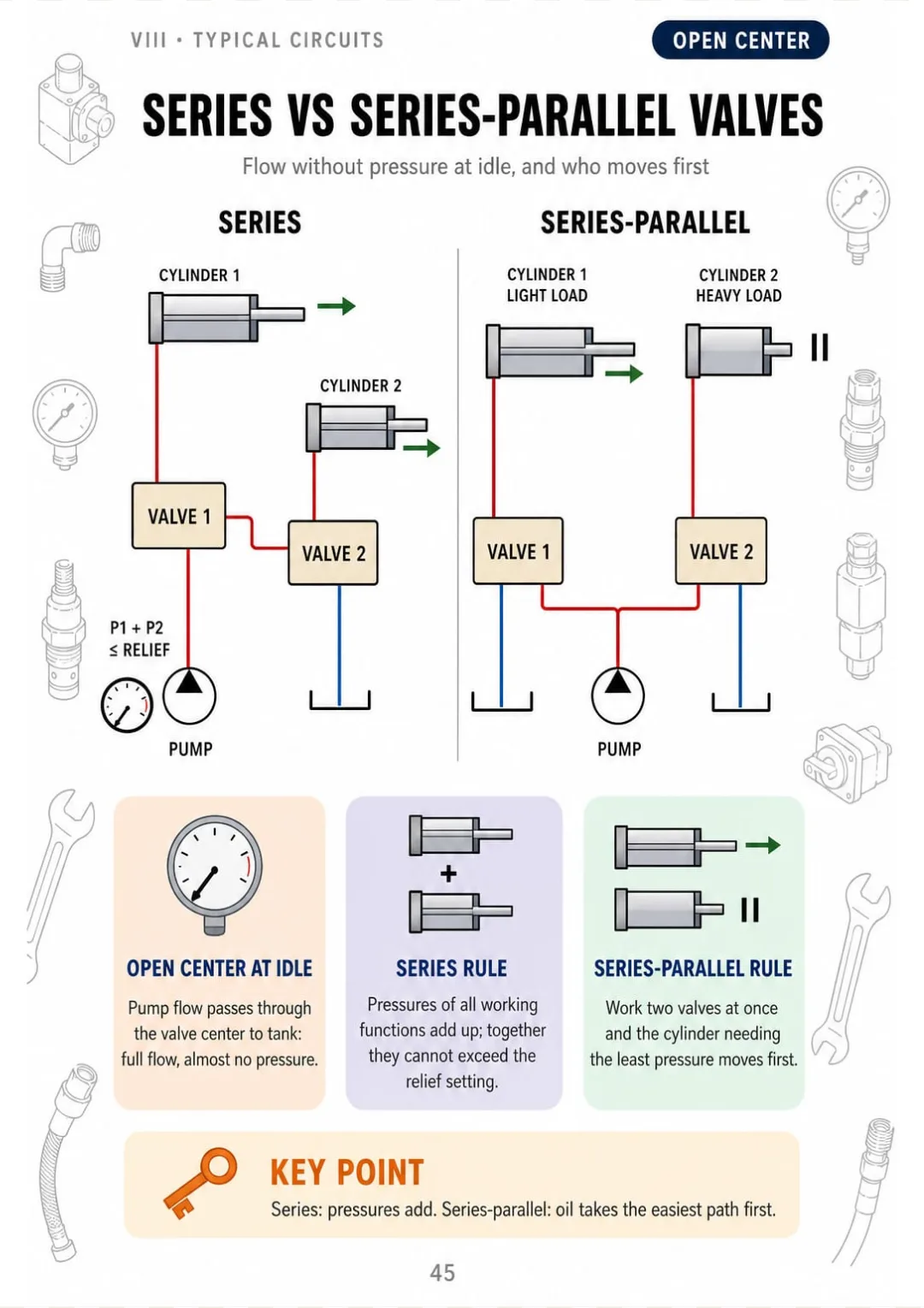
Series valves add pressures up to the relief setting; in series-parallel, the lightest load moves first.

Swipe to see more →

These are real pages from the book. The table of contents is the full one: 11 parts and 62 topics.

Nobody Ever Put It in Order for You.

The loader bucket creeps down with the lever in neutral. You open the schematic...

...and all you see is boxes, arrows and dashed lines. So you start swapping parts, hoping the next one fixes it.

Stationary tank rule of thumb: 2 to 3 times pump gpm, with a baffle between return and suction.

Here every part of that circuit is one page, drawn open. The tank, for example: it stores the oil, sheds heat, lets air and dirt settle out, and a baffle keeps the return away from the suction. For a stationary tank, the rule of thumb is 2 to 3 times pump gpm.

And on the pages next to it, every component gets its own: the filter, the pump, the relief valve, the 4/3 valve and the cylinder.

First you see why it works that way. Then following the oil just comes naturally.

SEE THE DIFFERENCE

Stop memorizing circuits you can't picture:

THIS
  • Pages and pages of tight text
  • Valves and circuits without a single drawing
  • At the machine, you don't know where to start
Pascal's Law states that pressure applied to a confined fluid is transmitted undiminished in all directions and acts with equal force on equal areas, at right angles to the walls of the container. Consequently, when an input force acting upon a small piston generates a given pressure, that same pressure acting upon a larger piston produces a proportionally greater output force, the multiplication being equal to the ratio of the piston areas, while the travel of the larger piston is reduced in inverse proportion.
FOR THIS
  • Every circuit drawn
  • One topic per page, with the rules in boxes
  • You remember it because you've seen it
2,000 psi on 1.77 in² = 3,534 lbf; on 7.07 in² = 14,137 lbf.
CONTENTS

Take a Look at the 11 Parts and 62 Topics

Reading a schematic, pressure and flow, reservoir and pumps, pressure controls, check and directional valves, 4/3 centers and flow control, actuators and accumulators, typical circuits, troubleshooting, safety and pneumatics: 66 pages, all drawn

IHow to Read a Schematic · pp. 5-10
  1. How to Use This Sketchbook
  2. Pictorial, Cutaway and Schematic Drawings
  3. Symbols Show Function, Not Construction
  4. Working, Pilot, Drain and Flexible Lines
  5. Crossing Lines, Junction Dots and Enclosures
  6. Tracing Oil From Tank to Actuator and Back
IIPressure, Flow and the Core Formulas · pp. 11-16
  1. Pascal's Law and Force Multiplication
  2. Pressure Comes From Resistance to Flow
  3. Gauge, Absolute and Atmospheric Pressure
  4. Force Equals Pressure Times Area
  5. Cylinder Speed Equals Flow Divided by Area
  6. Hydraulic Horsepower and Psi-Bar Conversions
IIIReservoir, Filters and Pumps · pp. 17-22
  1. The Reservoir and Its Jobs
  2. Reservoir, Filter and Cooler Symbols
  3. Full-Flow Filters, Ratings and Indicators
  4. Pump Symbols: Fixed, Variable, Reversible
  5. Gear, Vane and Piston Pumps
  6. Pump Output From Displacement and Rpm
IVPressure Control Valves · pp. 23-28
  1. The Simple Relief Valve
  2. The Pilot-Operated Relief Valve
  3. Unloading Valves and Pump Rest
  4. The Pressure-Reducing Valve
  5. The Sequence Valve
  6. The Counterbalance Valve
VCheck and Directional Valves · pp. 29-33
  1. Check Valves and Orifice Checks
  2. Pilot-Operated Check Valves
  3. Reading Envelopes: Ports and Positions
  4. 2/2, 3/2 and 4/2 Directional Valves
  5. Valve Operators: Lever, Spring, Detent, Solenoid
VI4/3 Centers and Flow Control · pp. 34-38
  1. Open-Center and Tandem-Center Spools
  2. Closed-Center Spools
  3. Float Center and the Loader Float Detent
  4. Flow Control Valves: Fixed to Compensated
  5. Meter-In, Meter-Out and Bleed-Off
VIICylinders, Motors and Accumulators · pp. 39-44
  1. Single-Acting Cylinders
  2. Double-Acting and Double-Rod Cylinders
  3. Cushioned and Telescoping Cylinders
  4. Hydraulic Motors: Speed and Torque
  5. Bladder, Piston and Spring Accumulators
  6. What an Accumulator Does in a Circuit
VIIITypical Circuits · pp. 45-50
  1. Open-Center Series and Series-Parallel Valves
  2. Closed-Center System With Variable Pump
  3. Regenerative Extension Circuit
  4. Front Loader: Boom, Bucket and Float
  5. Tractor Circuits: Steering, Hitch, Remotes
  6. Press Circuit With Sequence and Counterbalance
IXTroubleshooting From the Schematic · pp. 51-56
  1. The STOP Method and Flow-Pressure Testing
  2. Cylinder That Drifts Down Under Load
  3. Slow or Weak Actuator
  4. Oil Running Hot
  5. Cavitation vs Aeration
  6. Noisy Pump or No Delivery
XSafety Around Pressurized Oil · pp. 57-61
  1. Stored Energy and Lockout
  2. Lower, Block and Relieve Pressure
  3. Fluid Injection Injuries
  4. Pinhole Leaks: Cardboard, Not Hands
  5. Discharging Accumulators Before Service
XIPneumatics as an Extension · pp. 62-66
  1. Hydraulics vs Pneumatics: Exhaust to Air
  2. Boyle's Law and Absolute Pressure
  3. Compressor, Receiver and Moisture Removal
  4. Air Valves and Air Cylinders
  5. Compressed Air Cleaning Under 30 Psi

What If Every Topic Fit on a Single Page?

Imagine this:

Instead of rereading half a page about open, tandem and closed centers without being able to picture them...

...you open the page and find the spools drawn side by side, each with its symbol, where the pump oil goes and whether the cylinder holds.

Check valve vs orifice check: free flow one way, blocked or metered back

And relief valves, check valves, cylinders, accumulators and loader circuits turn into drawings and tables you can read at a glance.

You stop repeating and start understanding.

That's exactly what The Hydraulic Schematics Sketchbook does: 66 drawn pages in 11 parts, from the first symbol to troubleshooting from the schematic, every circuit traced in the same 5 steps. Because what you see in order, you remember.

Because what your brain sees organized, it remembers.

Here Is What You Get with The Hydraulic Schematics Sketchbook:

Ipp. 5-10

How to Read a Schematic

The three kinds of drawings, why symbols show function, working, pilot and drain lines, junction dots, and how to trace oil from tank to actuator and back.

IIpp. 11-16

Pressure, Flow and the Core Formulas

Pascal's law, why pressure comes from resistance, gauge vs absolute pressure, force = pressure × area, speed = flow ÷ area, and hydraulic horsepower.

IIIpp. 17-22

Reservoir, Filters and Pumps

What the reservoir does, filter and cooler symbols, filter ratings and indicators, fixed and variable pump symbols, gear, vane and piston pumps, and pump output.

IVpp. 23-28

Pressure Control Valves

Simple and pilot-operated relief valves, unloading valves, pressure-reducing, sequence and counterbalance valves, each with its symbol and cutaway.

Vpp. 29-33

Check and Directional Valves

Check and orifice checks, pilot-operated checks, how to read envelopes and ports, 2/2, 3/2 and 4/2 valves, and levers, springs, detents and solenoids.

VIpp. 34-38

4/3 Centers and Flow Control

Open, tandem, closed and float centers, the loader float detent, flow controls from fixed to compensated, and meter-in, meter-out and bleed-off.

VIIpp. 39-44

Cylinders, Motors and Accumulators

Single-acting, double-acting, cushioned and telescoping cylinders, motor speed and torque, and bladder, piston and spring accumulators in a circuit.

VIIIpp. 45-50

Typical Circuits

Series and series-parallel valves, closed-center systems with a variable pump, regenerative extension, the front loader, tractor circuits and a press circuit.

IXpp. 51-56

Troubleshooting From the Schematic

The STOP method and flow-pressure testing, then cylinder drift, slow actuators, hot oil, cavitation vs aeration, and noisy pumps, traced from the schematic.

Xpp. 57-61

Safety Around Pressurized Oil

Stored energy and lockout, lowering, blocking and relieving pressure, fluid injection injuries, checking pinhole leaks with cardboard, and discharging accumulators.

XIpp. 62-66

Pneumatics as an Extension

Hydraulics vs pneumatics, Boyle's law, compressor, receiver and moisture removal, air valves and cylinders, and compressed-air cleaning under 30 psi.


And That Is Not All: 2 More Books, Free

The Symbol Wall Chart

BONUS 1: «The Symbol Wall Chart»

Value on its own: US$ 17.90

One printable poster with every symbol in the book and its one-line meaning, so you can tape it up in the shop and check a symbol at a glance.

250 Hydraulics Terms on Cards

BONUS 2: «250 Hydraulics Terms on Cards»

Value on its own: US$ 14.90

Term on the front, a one-line definition and a tiny sketch on the back, so you can review the words that get mixed up (relief vs reducing, cavitation vs aeration) in a few minutes a day.

The Hydraulic Schematics Sketchbook + 2 Free Books

  • The Hydraulic Schematics Sketchbook: 66 illustrated pagesUS$ 87
  • BONUS 1: The Symbol Wall ChartUS$ 17.90
  • BONUS 2: 250 Hydraulics Terms on CardsUS$ 14.90
  • High-resolution PDF to printIncluded
Total value US$ 119.80
YOUR PRICE:
US$ 37
You save US$ 82.80
YES, I WANT THE HYDRAULIC SCHEMATICS SKETCHBOOK FOR US$ 37

📄 This is a digital PDF book sent to your email: nothing is printed or shipped.

Secure purchaseEncrypted payment30-day guarantee

PDF by email: The Hydraulic Schematics Sketchbook reaches your inbox as a PDF, and the two free books come by email too. One-time payment, no installments or hidden costs.

Is This Book for You?

You're learning the trade or retraining

You're learning the trade or retraining

Symbols, pressure, valves and circuits, one topic per page, so you can review between jobs and build the reading from the ground up.

A machine is down and someone's waiting

A machine is down and someone's waiting

Six common faults traced from the schematic, so you can reason out drift, slowness, heat or noise before you start taking things apart.

You already work on hydraulic equipment

You already work on hydraulic equipment

A quick, visual refresher of what you see every day: 4/3 centers, counterbalance, regenerative circuits, loader float and lockout.

To Sum Up: Here Is What You Get

US$ 119.80US$ 37
YES, I WANT THE HYDRAULIC SCHEMATICS SKETCHBOOK FOR US$ 37

📄 This is a digital PDF book sent to your email: nothing is printed or shipped.

30DAYS
GUARANTEE

30-Day Guarantee

30-day guarantee: tell us what didn't work and we'll refund 100%.

You have 30 days to try The Hydraulic Schematics Sketchbook and the two bonus books. If it doesn't work for you, tell us what didn't work and we'll refund 100% of what you paid. One-time payment, no subscription.

Frequently Asked Questions

How do I get the material?

You get The Hydraulic Schematics Sketchbook as a high-resolution PDF by email, sent to the address you enter at checkout, to read on your phone or print. The two bonus books, The Symbol Wall Chart and 250 Hydraulics Terms on Cards, come by email too.

I already have my machine's manual and YouTube. What does this add?

Your manual tells you what your machine has. This teaches you to read any schematic the same way every time, pump, relief, valve, cylinder, tank, with one drawn page per concept, all in one place and in order, instead of ten videos that each say something different. It works alongside your manual, never instead of it. One-time payment, no subscription.

Who is it for, and will it work for my tractor or brand?

For maintenance mechanics, heavy equipment and ag technicians, and owners who work on their own tractor, loader or log splitter. It isn't a service manual for any brand: it teaches you to read generic schematics and reason through faults, so it works alongside your machine's manual. Check the table of contents above to see the topics.

What sources is it based on?

On US Army FM 5-499 “Hydraulics” and US Navy NAVEDTRA 12964 “Fluid Power” for the technical content, OSHA 29 CFR 1910.147, 1926.600 and 1910.242(b) for safety, and NIST SP 811 for units. Symbol concepts follow the ISO 1219-1 style; no figures from the standard are reproduced.

Is it official material?

No. These are our own original teaching drawings. We aren't affiliated with or endorsed by ISO, NFPA, OSHA or any equipment manufacturer, and we don't reproduce manufacturer documents.

Does it replace training or the service manual?

No. It's study material. It doesn't replace hands-on training, your machine's service manual, your employer's procedures or lockout/tagout. Always follow the manual for your machine.

Is it prep for a certification exam?

No. There's no exam behind this book and it contains no official exam questions. It teaches you to read schematics and understand the machine.

Can I print it?

Yes. It's a printable PDF, so you can keep the pages, or the symbol chart, in the shop or the toolbox.

What if I don't like it?

30-day guarantee: tell us what didn't work and we'll refund 100%.

One Last Thing Before You Decide...

You don't have to reread the same page hoping it sticks this time.

You don't have to memorize symbols you can't picture.

And you definitely don't have to stand at a stopped machine without knowing where to start.

There's a simpler way. And it's one click away. Now it's your turn.

One-time payment: US$ 37 · Guarantee: 30 days · PDF by email

YES, I WANT THE HYDRAULIC SCHEMATICS SKETCHBOOK FOR US$ 37

📄 This is a digital PDF book sent to your email: nothing is printed or shipped.